04 / Simulation capabilities

Materials, processes and models.

Platform capabilities and planned workflows. Confirm availability and application suitability with DTVL.

01 / Powder processing

Die Compaction

Configuration prototype; numerical execution is not connected.

Tooling-driven densification of powder in a die using punch loading, including unloading and ejection behaviour.

DTVL supports simulation of powder compaction for pharmaceutical powders, ceramic powders, metal powders / powder metallurgy and other compactable particulate materials exhibiting pressure-driven densification, where the constitutive model and parameters are suitable. The workflow can represent evolving nonlinear elastic behaviour, including stiffness and Poisson’s ratio dependence on relative density and pressure, together with configurable tooling, geometry and friction conditions.

Mechanical analysis can use an elastic-only response or supported plasticity such as Drucker–Prager Cap. Optional thermal coupling can investigate temperature evolution and thermo-mechanical behaviour during compaction, where supported by the selected workflow and material model.

The modelling approach builds on doctoral constitutive-model research at the University of Leicester under the supervision of Prof. Csaba Sinka.

Configurable compact geometry and tooling

Pharmaceutical tablets are one application family: supported setups can include circular and oval tablets with prescribed dimensions, flat or curved/ball-type punch faces, and optional score or central division features. The same workflow can represent typical ceramic and powder-metallurgy components produced by die pressing, subject to suitable models, parameters and tooling. Guided inputs define a family of compact designs rather than a single fixed component.

More complex components may require multi-punch, core-rod or other specialised tooling configurations.

Conceptual figure placeholder
Circular tablet
Oval tablet
Scored tablet
Configurable tablet geometry

Tablet dimensions, shape, punch profile and score features can be defined through the DTVL workflow.

Conceptual schematics / Not simulation results

Representative die-compacted geometries

Circular tablet
Oval tablet
Annular / ring compact
Cylindrical compact with side hole
Stepped cylindrical compact
Representative compact geometries

Representative die-compacted geometries span pharmaceutical, ceramic and powder-metallurgy applications.

Configurable contact and friction

Tool–material interaction can be represented using different levels of friction modelling, from a constant friction coefficient to state-dependent formulations. Where supported by appropriate calibration data, friction may vary with contact pressure, relative density, or both.

A static-to-kinetic transition can also be represented, allowing a higher friction coefficient while the interface is sticking or before relative sliding begins, followed by a lower sliding-friction response that can subsequently evolve with contact pressure.

p represents contact pressure; RD represents relative density.

State-dependent friction laws require suitable experimental calibration and are not assumed to be universal across materials and tooling conditions.
Constant friction
μ = constant
State-dependent friction
μ = f(p, RD)
Static → kinetic friction
μstatic → μkinetic = f(p)after sliding begins
01 / Powder processing

Isostatic / Hydrostatic Compaction

Configuration prototype; numerical execution is not connected.

Pressure-driven densification of powder bodies under distributed surface pressure without explicit punch-and-die pressing.

Compaction can also be represented under approximately hydrostatic or isostatic pressure loading, where the component is densified through pressure acting around its external surface rather than predominantly through rigid punch-and-die loading.

Cold Isostatic Pressing and hydrostatic loading have a frontend configuration prototype; solver support and application-specific suitability require implementation and validation. HIP is a separate geometry prototype involving pressure, elevated temperature and time-dependent densification; full numerical execution remains under development.

01 / Powder processing

Roll Compaction

Continuum simulation of powder densification between counter-rotating rolls using a Lagrangian finite-element formulation.

The current DTVL workflow uses a finite powder domain with defined feed geometry, roll-gap conditions, material behaviour and powder–roll interaction. The computational mesh follows the deforming powder. Very large material transport through the roll gap may eventually produce excessive mesh distortion; practical deformation limits depend on geometry, material behaviour, contact conditions and mesh resolution.

Analysis scope

2D plane-strain configuration with rigid upper and lower rolls and a deformable powder continuum. The emerging ribbon is the same powder material after deformation. The current formulation does not provide unlimited continuous material inflow and outflow. 3D configuration is planned.

Representative inputs

  • Finite feed geometry, roll radius and gap, powder-bed height and initial position relative to the nip
  • Elastic and plastic/cap material response, including relative-density and pressure dependencies where applicable
  • Stage-linked roll rotation, positioning constraints, feed-side boundary conditions and powder–roll friction
  • Automatic, coarse, medium or fine mesh presets, with planned refinement around the nip and contact regions

Representative outputs

  • Ribbon relative density and density distribution through ribbon thickness
  • Ribbon thickness, stress, strain, plastic strain and displacement
  • Roll force, roll torque, contact pressure and frictional response

Engineering guidance and prototype status

The current Lagrangian formulation is best suited to configurations for which acceptable mesh quality can be maintained through the required deformation. Generated-model assessment and analysis execution are not yet connected in the customer configurator; no calculated results or validated deformation limits are claimed. Mesh-distortion monitoring and large-deformation capability will expand as numerical methods are validated.

01 / Powder processing

Post-Compaction Integrity & Damage Analysis

Advanced analysis of unloading, punch withdrawal and ejection from a saved compacted-state checkpoint. The intended workflow investigates springback, residual stresses, failure initiation, progressive material degradation and, where supported, element deletion without repeating the preceding compaction simulation.

Alternative integrity and damage formulations can be applied to the same compacted state for comparative studies. Die Compaction → saved peak-compaction checkpoint → Post-Compaction Integrity & Damage Analysis. The source job may have completed later stages; the branch starts from the chosen saved checkpoint.

Current controls are prototype configuration only. State transfer, damage initiation and evolution, degradation, regularisation and element deletion are under development and validation. Visible simulation results alone do not contain the complete saved process state.

The underlying approach builds on experimental and numerical investigation of capping during unloading and ejection in pharmaceutical tablet manufacture undertaken during doctoral research at the University of Leicester. Capping is a demonstrated application rather than the full scope of this capability.

Crack prediction requires an appropriately validated damage model; critical stress or localisation alone does not guarantee prediction of cracking.

Thermal & Coupled Processing

Flash Sintering

Supported availability
Supported PhysicsElectricalThermalMechanical
Mechanical response classesViscoplastic

Research-stage / mSO only

Research-stage / mSO only. Exploratory configuration for electrical conduction, Joule heating, thermal transport and mSO-based sintering. Numerical coupling and analysis execution are not connected.

Exploratory scope

Configure specimen geometry, electrode regions, electrical histories, thermal conditions and mSO-based sintering response. Supported physics are Electrical [EL], Thermal [T] and Mechanical [M]. The selected mSO continuum formulation supplies Viscoplastic [VP] response; elastic response is not included in this formulation.

Research limitations

This workflow is not a universally validated flash-sintering model. Coupled numerical execution, control transitions and calculated results are not yet available. Application suitability requires material-specific validation.

02 / Process

Sintering

Configuration prototype; numerical execution is not connected.

Thermally driven densification, shrinkage and shape evolution under internal sintering stresses and applicable mechanical constraints.

Model densification, shrinkage and deformation during sintering.

Where supported, external loads, gravity, applied pressure and fixture/support reactions can influence deformation. Mechanical deformation can be driven by internal sintering stress as well as external loads, gravity, supports or constraints. Viscoplastic is a mechanical response class; external loading is optional. A prescribed temperature history does not necessarily involve a solved thermal field. Coupling availability depends on the selected workflow and material model.

Customer-defined sintering models

Standard sintering workflows can represent common component geometries and process conditions. For bespoke engineering projects, DTVL can develop models around customer-specific component geometry, internal and external features, material definitions, thermal histories, supports, contact conditions and other application-specific requirements.

Bespoke geometries and engineering workflows developed for a customer can be restricted to that customer’s private DTVL environment and are not made available to other customers.

S02 / Figure placeholder

Sintering — dilatometer sample

Reserved for a real technical figure.

Image to be supplied
Dilatometer sintering

Thermal densification and shrinkage are predicted for a dilatometer specimen.

S03 / Figure placeholder

Sintering — beam bending under gravity

Reserved for a real technical figure.

Image to be supplied
Gravity-driven beam bending

Sintering predictions describe shape evolution and deflection under gravity.

03 / Coupled process

Die Compaction + Sintering

Configuration prototype; numerical execution is not connected.

Sequential simulation of die compaction, green-body state transfer and subsequent sintering.

Coupling availability depends on the selected workflow and material model. This sequential workflow uses die compaction as its first stage. Initial powder → Die compaction → Unloading/ejection → Green compact → Heating → Sintering. Subsequent sintering can inherit final geometry, relative density and compatible stress, plastic/state and history variables where supported. Prototype configuration records transfer requests; it does not generate or transfer computed solver state.

Standard configurable workflows cover supported process families. Bespoke coupled workflows can be developed for customer-defined component geometry, internal and external features, tooling, pressure histories, thermal cycles, supports, contact conditions and other application-specific requirements.

Customer-specific coupled models can be deployed only within the requesting customer’s private DTVL environment.

S01 / Figure placeholder

Die compaction sequence

Reserved for a real technical figure.

Image to be supplied
Die compaction sequence

Relative density and deformation are tracked through initial setup, loading, unloading, punch removal and ejection.

Thermal & Coupled Processing

Isostatic / Hydrostatic Compaction + Sintering

Supported
PhysicsMechanicalThermal
Mechanical response classesElasticPlasticViscoplastic

Sequential simulation of pressure-driven compaction, green-body state transfer and subsequent sintering.

Frontend configuration prototype. Initial powder → Isostatic/hydrostatic pressure compaction → Unloading → Green compact → Heating → Sintering. Green-body geometry, relative density and compatible stress/plastic/history variables can be requested for transfer where supported; no computed state transfer occurs in the prototype.

Thermal & Coupled Processing

Hot Isostatic Pressing (HIP)

Supported
PhysicsMechanicalThermal
Mechanical response classesElasticPlasticViscoplastic

Coupled pressure- and temperature-driven densification under simultaneous thermal and mechanical loading.

Geometry & Bodies prototype for pressure, temperature and time-dependent densification. Full process configuration, material formulations and numerical execution remain under development. HIP combines pressure and heating over time; it is distinct from cold isostatic compaction. Badges describe intended availability subject to implementation and validation.

04 / Formulation

Powder Formulation Design

Mixture-rule-based prediction for mechanically compacted multi-component powder systems

DTVL can support formulation design for multi-component powder systems undergoing mechanical compaction. Component-level compaction behaviour is combined using mixture rules to estimate formulation response across composition and processing conditions.

Potential applications include pharmaceutical powders, ceramic powder mixtures, metallic powder mixtures and other compactable particulate systems. The methodology has been demonstrated for pharmaceutical tablet formulation; application to other compacted powder systems requires suitable component-level data and validation. Predictive accuracy depends on whether the mixture rule adequately represents interactions between constituents.

Depending on the application, a feasible design window can be based on prescribed mechanical, compaction or manufacturing criteria, including strength, ejection behaviour, relative density, compaction-pressure limits and other validated criteria.

DTVL builds on the Successful Formulation Window methodology developed during doctoral research at the University of Leicester under the supervision of Prof. Csaba Sinka, with industrial collaboration from AstraZeneca. This academic origin is distinct from DTVL platform development.

The current methodology addresses mechanical and manufacturability criteria. Additional pharmaceutical quality attributes require separate models and validation.

Demonstrated application: pharmaceutical tablets

From component behaviour to mixture prediction

Component-level compaction behaviour provides the starting point. Rules of mixtures combine the constituent responses according to formulation composition.

The design space links composition and compaction pressure to supported mechanical and manufacturability requirements.

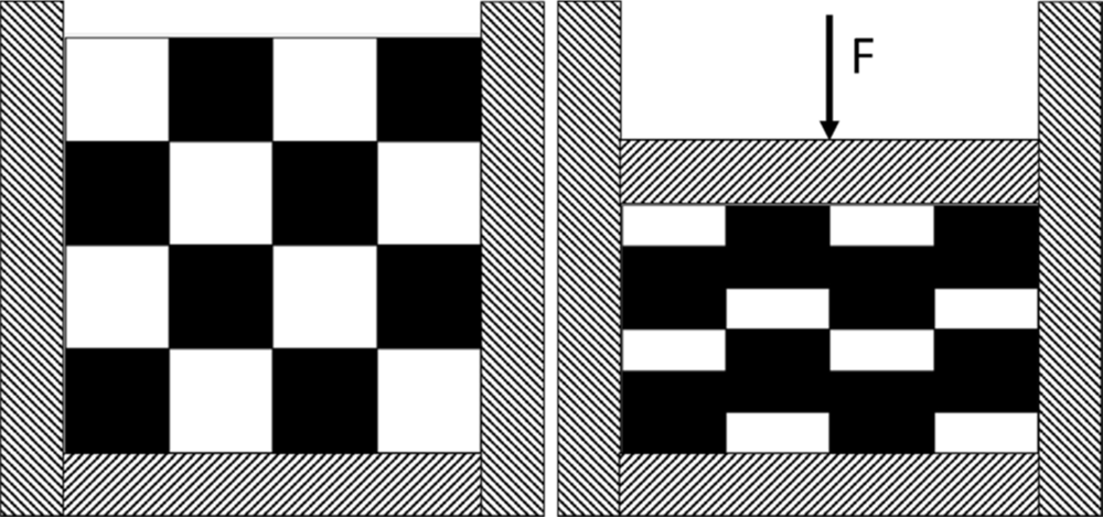
Two-constituent mixture before and after compression in a die; the constituents show different volume reductions under the applied load.
Mixture-rule concept

Component-level densification behaviour is combined according to composition to predict formulation response.

Explore the formulation design space

Identify the Successful Formulation Window

  1. 01 — Define formulation

    Select constituent materials and composition ranges.

  2. 02 — Define requirements

    Specify supported mechanical and processing limits such as minimum tablet strength, maximum ejection stress and maximum compaction pressure.

  3. 03 — Calculate feasible region

    Evaluate the design space and identify the Successful Formulation Window.

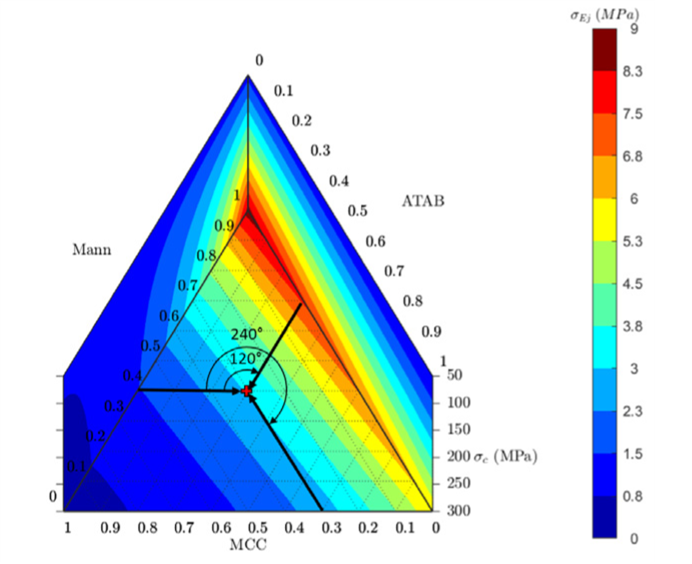
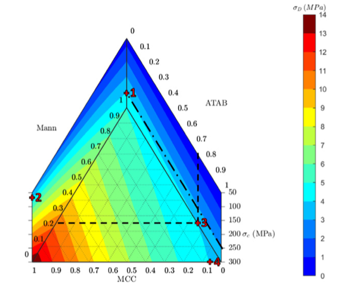
Tablet-strength colour map across ternary Mann, ATAB and MCC composition and compaction pressure, with strength shown in MPa.
Tablet strength

Predicted mechanical performance across formulation composition and compaction pressure.

Ejection-stress colour map across ternary Mann, ATAB and MCC composition and compaction pressure, with ejection stress shown in MPa.
Ejection stress

Predicted ejection behaviour across formulation composition and compaction pressure.

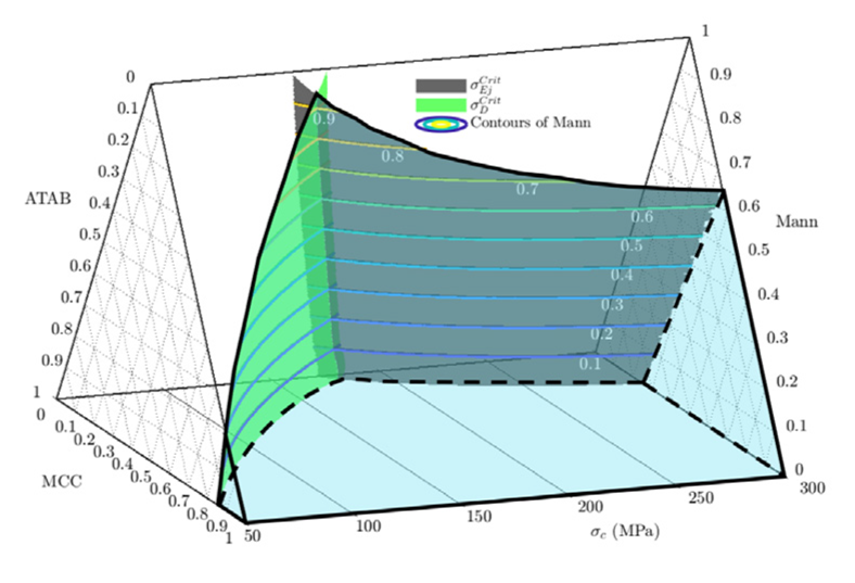
Three-dimensional Successful Formulation Window showing a feasible region bounded by tablet-strength and ejection-stress constraints across composition and compaction pressure.
Successful Formulation Window

Feasible composition–processing region satisfying the prescribed mechanical and manufacturing constraints.

05 / Product process simulation

Kiln & Furnace Process Simulation

Thermal and thermomechanical simulation of products during kiln and furnace processing, including transient heating, thermal gradients, mechanical restraint, support interaction and, where applicable, sintering-driven densification and distortion.

Analysis scope can range from thermal-only heating studies to coupled product sintering with supports and thermal contact. Supported physics are Mechanical [M] and Thermal [T], with Elastic [E], Plastic [P] and Viscoplastic [VP] material responses where applicable. Supported capabilities do not require every response to be active.

Choose the analysis scope

  • Thermal only: transient product heating and cooling, temperature gradients and heat flux.
  • Thermal + mechanical deformation: thermal expansion, mechanical restraint, support interaction, thermally induced stress and distortion.
  • Thermal + sintering: product temperature drives the selected sintering material response, including relative-density evolution, shrinkage and sintering stress.
  • Thermal + sintering + supports/contact: product, setter, support or fixture interactions, including mechanical friction and thermal conductance or gap heat transfer.

Furnace environment and cycle

Heat → Hold → Cool stages define process timing. Ambient or wall temperature histories, convection, radiation, prescribed product temperature and heat flux define the applied thermal environment. A simplified environment can apply conditions directly to the product without explicitly meshing the furnace.

Materials and coupling

Thermal properties and applicable mechanical responses use shared DTVL material definitions. Sintering configurations reuse the MSO material structure and optional, separate Grain Growth model. Elastic and Plastic are activated only where the selected formulation needs them.

Staggered processing transfers the thermal field to the mechanical/sintering analysis. An iterative coupling request describes feedback through changing geometry, contact and thermal gaps. These are prototype configuration options; production execution and calculated results are not implemented in the current web configurator.

Product and process inputs

  • Product geometry, dimensions, orientation and placement
  • Initial product temperature and relevant material properties
  • Furnace temperature cycle and thermal boundary definitions
  • Setter, support or fixture configuration where applicable
  • Calibrated sintering parameters and Grain Growth definition where active

Chamber, custom geometry and multi-product arrangements are configuration placeholders where execution is unavailable. Gas flow and combustion are future capabilities; the current atmosphere is represented through thermal boundary conditions.

  1. Furnace environment and cycle
  2. Product temperature field
  3. Applicable mechanical / sintering response
  4. Densification, shrinkage and distortion
06 / Nonlinear continuum FEA

Bulk Solids & Silo Flow

Configuration prototype for silo/hopper stress, wall loads, gravity settling, outlet opening and incipient or early discharge. Numerical execution is not connected.

The configuration records cohesion, internal friction, wall friction, density, compressibility and constitutive parameters for future assessment of stress and wall loading. Arching and stagnant-region predictions are planned and require validation.

Full silo emptying, die filling and large material transport remain future large-deformation capabilities.

Representative inputs

  • Silo / hopper geometry
  • Outlet size and shape
  • Wall friction
  • Bulk density
  • Cohesion
  • Internal friction
  • Constitutive material parameters

Requested outputs — numerical execution unavailable

  • Stress distribution
  • Wall pressure
  • Deformation field
  • Shear localisation
  • Stagnant regions — planned
  • Outlet-region behaviour
  1. Material properties + silo geometry + wall conditions
  2. Nonlinear continuum FEA
  3. Stress / localisation / wall loading / discharge behaviour
04 / Parameters

Constitutive Model Calibration & Parameter Identification

DPC configuration and coverage checks available; numerical calibration under development.

Experimental Data Analysis converts raw measurements into engineering quantities; Constitutive Model Calibration uses those quantities to identify parameters of a selected material model.

DPC experiment setup, calibration/validation assignment and experimental coverage checks. Numerical calibration is under development.

Model-dependent / future calibration targets

  • Modified Skorohod–Olevsky sintering model
  • Cocks-type sintering models
  • Drucker–Prager Cap (DPC)
  • Cam-Clay-type models
  • Gurson-type porous plasticity
  • Other supported constitutive formulations where suitable experimental data are available

Availability and identifiable quantities depend on the selected model, supported workflow and experimental evidence.

Powder compaction / DPC

Candidate quantities depend on independent experimental evidence; numerical identification is not connected. These may include:

  • Young’s modulus as a function of relative density, temperature and pressure
  • Poisson’s ratio as a function of relative density, temperature and pressure
  • Cap and pressure-sensitive plasticity parameters
  • Density-dependent DPC parameters
  • Other state-dependent quantities where supported by data

Sintering models

Depending on the selected constitutive formulation and available experiments, calibration can address parameters governing bulk viscosity, shear viscosity, sintering stress, temperature and relative-density dependence, and grain-growth kinetics.

Where suitable grain-size measurements are available across temperature or firing history, DTVL can support identification of parameters governing the grain-growth law and its coupling to the sintering constitutive response.

  • Bulk viscosity parameters
  • Shear viscosity parameters
  • Sintering-stress parameters
  • Temperature dependence
  • Relative-density dependence
  • Grain-growth kinetic parameters
  • Coupling between grain growth and constitutive response where supported by the selected model

Powder compaction calibration

Instrumented die-compaction, strength and shear-test data can be combined to identify density-dependent elasticity and pressure-sensitive plasticity parameters.

Sintering calibration

Dilatometry and mechanically informative deformation tests can be combined to identify parameters governing volumetric densification and deviatoric resistance.

The parameters that can be identified depend on the information content of the available experiments. Additional complementary tests may be required where multiple parameter sets reproduce the same measured response.

  1. Experimental data
  2. Processed material response
  3. Constitutive model
  4. Parameter identification
  5. FE verification
Material characterisation / Test simulation

Mechanical Characterisation Test Simulation

Configuration prototype; numerical execution is not connected.

Material model configuration

The shared DTVL material configurator includes general linear elastic, perfectly plastic and isotropic-hardening inputs alongside specialised pressure-sensitive/porous plasticity and viscoplastic sintering configurations. Mechanical tests begin with a simple elastic material choice; plasticity is selected according to the specimen and test.

These are configuration prototypes. Constitutive evaluation and analysis execution are not connected in the customer web app. Additional formulations are introduced as their implementation and validation become available.

Guided finite-element simulation of standard mechanical characterisation tests using predefined specimen, loading, support and contact templates. The workflow reduces the need for manual model construction while retaining control over specimen dimensions, applied load or displacement, support geometry, friction and material behaviour.

Mechanical [M] is the initial physics scope. Elastic [E], Plastic [P] and compatible Viscoplastic [VP] responses are selected according to material formulation rather than imposed by test type. Thermal test variants are planned.

Initial guided test templates

  • Uniaxial Compression — cylindrical or rectangular specimen between platens
  • Uniaxial Tension — prismatic specimen with prescribed grip regions
  • Diametrical Compression / Brazilian Test — disc between platens
  • Three-Point Bending — central loading nose and two supports
  • Four-Point Bending — two loading noses and two supports
  • Simple Shear — restrained region and lateral loading

Guided configuration

Choose the test, specimen dimensions, compatible material definition, loading mode, support spacing and tooling radii where applicable. Stage-linked force, displacement or appropriate pressure loading uses the selected process duration. Required contacts are created by the template; friction controls appear only when contacting tooling is represented.

The shared Material page supports Elastic, DPC and compatible MSO definitions with applicable state dependencies. MSO is a porous/sintering viscoplastic model, not a general-purpose viscoplastic law. Additional failure, damage and other material formulations require implementation and validation.

Automatic, Coarse, Medium and Fine mesh presets request refinement near contact, loads, supports, small radii and high-gradient regions. Main View provides a simplified schematic; Live Model is reserved for actual generated geometry and mesh.

Representative outputs and plots

Generic requests include displacement, reaction force, stress, principal stress, strain, applicable plastic/inelastic strain and contact pressure. Test-specific requests include force–displacement, engineering stress–strain, indirect tensile stress, flexural stress/strain, load–deflection, shear stress–strain and support reactions.

Engineering reductions depend on suitable specimen dimensions, loading/contact assumptions and verified analysis data. True quantities require meaningful current dimensions; stress alone does not constitute a validated failure prediction. Additional damage/failure outputs will appear only when a supported active formulation supplies them.

Relationship to Experimental Data and Calibration

This module simulates the test numerically. Experimental Data Analysis & Material Characterisation processes measured test data. Constitutive Model Calibration & Parameter Identification can combine experimental and simulation results to identify material parameters.

Prototype status and future development

The six initial templates are interactive configuration prototypes. Model generation, numerical execution and standard test-result calculations are not connected; no calculated curves or validated characterisation results are claimed.

Confined Compression, Ring Compression, Indentation / Flat-Punch Compression, Punch / Shear Tests and fracture-specific tests are planned, not implemented. Dog-bone geometry and thermomechanical variants are also future extensions.

05 / Measurements

Experimental Data Analysis & Material Characterisation

Available processing for supported templates; test-specific limitations apply.

DTVL can analyse supported experimental datasets from powder, compact and material testing and convert raw measurements into engineering quantities suitable for interpretation, constitutive calibration and simulation.

Test-specific analysis availability

Supported DTVL templates provide processing and curve inspection. Planned analyses are distinguished in the Workspace; an uploaded file does not imply that every listed property can be calculated.

  • Diametrical compression
  • Uniaxial compression
  • Instrumented die compression
  • Schulze ring shear testing
  • Three-point bending
  • Four-point bending
  • Nanoindentation — selected unloading/contact-area reductions
  • Uniaxial tension
  • Simple / direct shear
  • Confined, triaxial and hydrostatic compression — planned

Representative outputs

  • Strength as a function of relative density
  • Axial and radial stress histories from instrumented die compression
  • Unloading/ejection-related response where available
  • Shear strength and Mohr–Coulomb-type failure envelopes where appropriate
  • Flexural strength / bending response
  • Indentation hardness and modulus, or other supported indentation quantities
  • Fitted material-property trends for constitutive calibration

Experimental data analysis can be used as a standalone service or as an input to parameter identification, constitutive-model calibration and Digital Twin workflows.

Supported file formats, required columns and test metadata depend on the selected analysis; arbitrary uploaded data are not assumed to be automatically analysable. Numerical constitutive-model identification is under development in the calibration workflow.

06 / Data methods

Machine Learning

ANN-Based Constitutive Modelling

DTVL uses artificial neural networks (ANNs) as computationally efficient representations of selected constitutive behaviour within finite-element workflows. ANN-based material models can reproduce selected constitutive responses and may reduce the computational cost associated with repeated evaluation of complex analytical material laws, subject to the architecture, implementation and required accuracy.

These surrogate models can support faster finite-element simulation, parameter studies, inverse identification and Digital Twin updating.

DTVL builds on UKRI-funded postdoctoral research at the University of Leicester into neural networks embedded within FEA. Published applications include constitutive-law replacement, data-assisted sintering deformation and multiphysics simulation, alongside calibration and digital-twin methods.

Research background

Representative ANN formulations

The architecture shown is one representative reduced-input ANN rather than the limit of the DTVL machine-learning framework.

  • Reduced-input constitutive surrogates
  • Extended-input ANN models using a larger or full set of constitutive/model parameters
  • ANN models incorporating relevant state variables and strain-rate information

A representative formulation can combine state variables with viscoplastic volumetric and deviatoric strain-rate measures to predict volumetric and deviatoric stress response. These are formulation directions, not a claim that every architecture is already a production workflow.

Beyond sintering

The ANN constitutive framework is not restricted to sintering. Where suitable training and validation data are available, similar surrogate approaches can be developed for elastic material behaviour, elastoplastic material models, Drucker–Prager Cap (DPC) type models and other supported nonlinear constitutive formulations.

Appropriate training data, parameter coverage, verification and application-specific validation are required. ANN surrogates do not automatically replace physics-based modelling or eliminate the need for calibration, and neither greater speed nor accuracy is guaranteed.

Planned research / Not a production capability

Planned advanced plasticity development

A planned research direction is the ANN-assisted implementation of Fleck-type advanced plasticity formulations within FEA. Such formulations are of interest for additional size-dependent behaviour; any treatment of surface-energy-related effects would depend on the selected formulation and its verification.

This development is not presented as implemented or validated in DTVL.

ANN capability directions

  • Constitutive-law surrogates
  • Reduced and extended ANN input spaces
  • State- and strain-rate-dependent ANN response
  • ANN acceleration of repeated FEA evaluations
  • Inverse identification and Digital Twin updating
  • Extension to elastic and plastic constitutive behaviour
  • Planned advanced plasticity developments
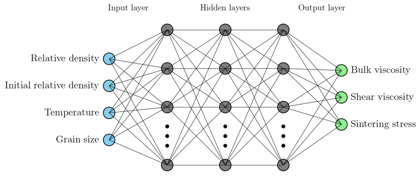
Representative KGS sintering ANN with relative density, initial relative density, temperature and grain size as inputs, and bulk viscosity, shear viscosity and sintering stress as outputs.
Representative KGS ANN surrogate

Example ANN constitutive surrogate mapping relative density, initial relative density, temperature and grain size to bulk viscosity, shear viscosity and sintering stress.

Digital Twin / Evidence-informed modelling

Digital Twin

Independent methods and observation channels

Physics-Based Constitutive Identification progressively constrains an admissible material-parameter population. ANN-Assisted Adaptive Digital Twin refines an embedded material representation through physics-guided directional updating. The methods share experimental observations without becoming a single opaque optimiser.

Observation channels include multi-rate dilatometry, optical beam-bending A(T), and registered final component geometry or scan-derived control points. The customer web app currently provides configuration and measured-data inspection; numerical identification, finite-element comparison and ANN updating are not connected.

Two complementary routes to model refinement.

DTVL supports two complementary Digital Twin approaches for model calibration and engineering interpretation. One calibrates a physics-based constitutive law through iterative parameter identification against experimental evidence. The other updates an ANN-based material representation using directional (sign-based) backpropagation informed by experiment–simulation mismatch. These workflows can also support boundary-condition prescription or refinement based on measured experimental behaviour. The geometries shown here are demonstrator examples only; the workflow can be adapted to customer-specific shapes, measurement definitions and calibration targets.

Connect measurements and computational models for comparison and refinement.

ROUTE 01 / CONSTITUTIVE CALIBRATION

Physics-Based Constitutive Identification

Configuration prototype; numerical execution is not connected.

Physics-Based Constitutive Identification

Multi-rate dilatometry supplies complementary volumetric constraints on temperature- and density-dependent constitutive response. Retain a population of admissible parameter sets, then use gravity-loaded beam bending or component distortion to discriminate mechanically informative, deviatoric response.

For optical beam bending, fit y(x) = A x² + B x + C and compare experimental and numerical A(T). Keep dilatometer and mechanical fit errors separate. The best individual candidate does not establish uniquely correct material properties.

Histograms, parameter correlations and admissible constitutive envelopes describe residual non-uniqueness when evaluated populations are available. Numerical search execution and calculated uncertainty displays are not connected in the customer web app.

A physics-based constitutive model is retained and calibrated through iterative comparison between simulation and experiments. Material parameters are identified using complementary evidence such as dilatometry and beam bending, helping reduce non-uniqueness and improve predictive confidence.

This route is suited to calibration of explicit constitutive descriptions where interpretable material parameters remain central to the workflow.

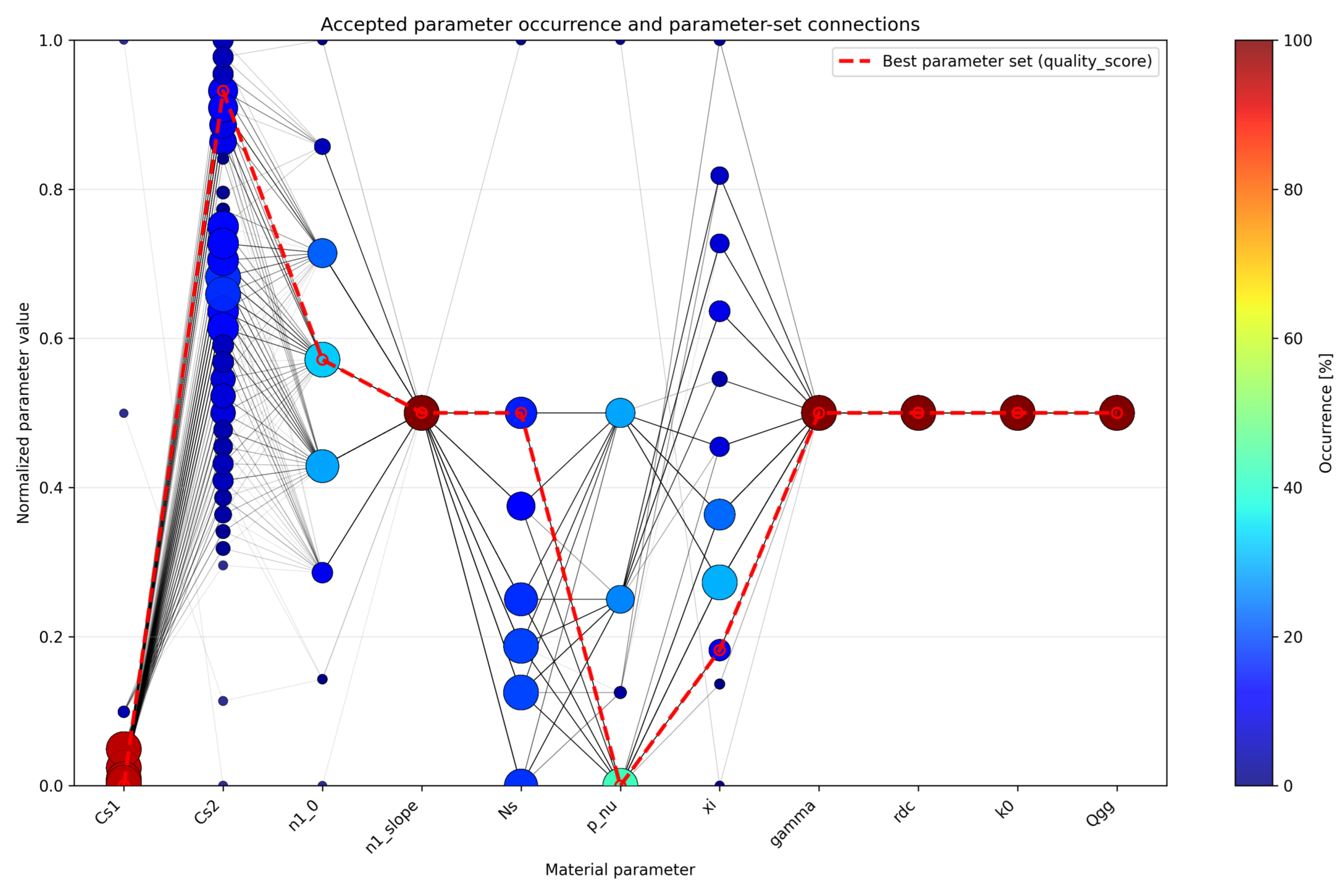
Accepted material parameter occurrences and connections between parameter sets, with the best-quality parameter set highlighted.
Parameter-space calibration

Accepted parameter sets are identified through iterative constitutive-law calibration against experimental observations.

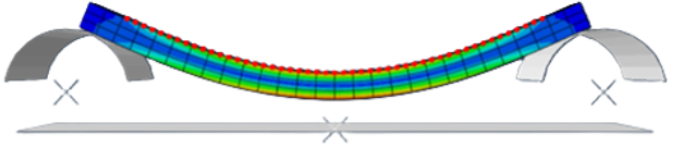
Finite-element beam-bending result on two supports, showing a deformed mesh and marked comparison points.
Beam-bending identification

Beam-bending simulation complements other measurements to improve identifiability and assess predictive consistency.

ROUTE 02 / ANN-ENABLED CALIBRATION

ANN-Assisted Adaptive Digital Twin

Configuration prototype; numerical execution is not connected.

ANN-Assisted Adaptive Digital Twin

A trained ANN is embedded within the simulation workflow and refined from experiment–simulation discrepancy through physics-guided directional updating. Physically inferred directional information supplies a heuristic sensitivity approximation; this does not require or claim exact differentiation through the complete finite-element simulation.

The configuration prototype restricts updates to shear-related response while keeping bulk viscosity and sintering stress fixed to preserve volumetric constraints. Registered component geometry is an experimental feedback channel; beam A(T) feedback requires a scientifically validated observable-to-update mapping.

Future developments include ANN forward surrogates, population-valued inverse surrogates, automatic optical image processing and uncertainty-guided next-experiment recommendations. These features are not currently implemented in the customer web app.

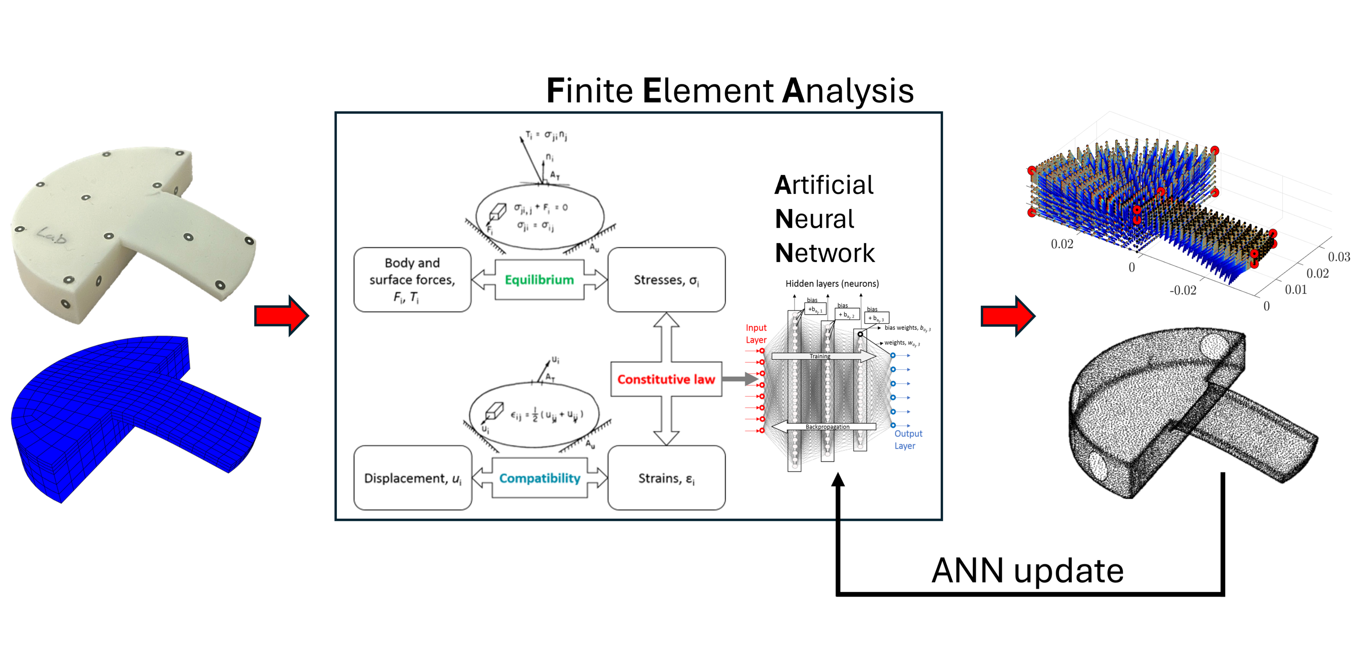
A neural-network material representation is embedded within the finite-element workflow and updated through directional (sign-based) backpropagation to reduce mismatch with experimental evidence. This route can use geometric measurements, control-point targets and scan-derived information to calibrate or refine the digital representation.

This approach is especially useful where the material representation benefits from ANN flexibility or where measured geometry and response are used directly within the update loop.

Schematic linking a measured component, finite-element model, embedded artificial neural network and an ANN update loop.
ANN calibration workflow

Directional backpropagation updates the embedded ANN representation from experiment–simulation mismatch.

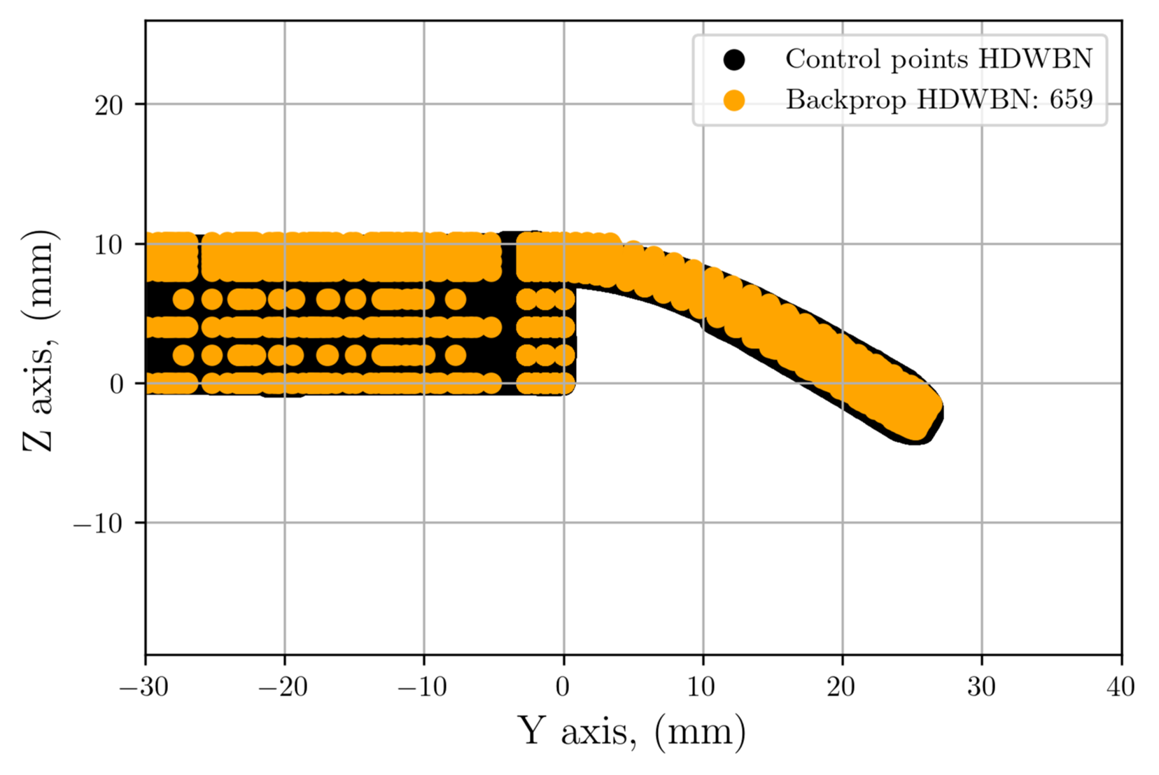
HDWBN control-point comparison in the Y–Z plane, showing target points in black and updated points in orange.
Geometry comparison

Target and updated control-point sets are compared for ANN-based Digital Twin calibration.

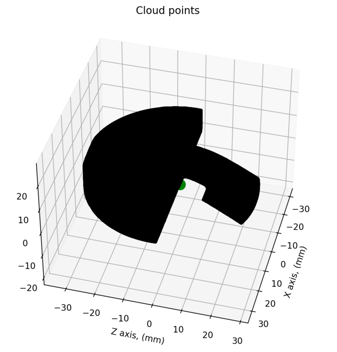
Three-dimensional HDWBN cloud-point representation of the same demonstrator geometry used in the control-point comparison.
Experimental scan

Scan-derived geometry or cloud-point evidence informs the ANN-enabled Digital Twin workflow.

The level of digital-twin integration depends on available measurements, model suitability and application. These workflows do not automatically provide continuous real-time updating; parameter identifiability and predictive agreement require verification and validation.

Research provenance and publication status

05 / Customer-specific workflows

Bespoke Engineering Models

The processes and geometries shown on the website represent standard and illustrative workflow families rather than the limits of the platform. Across supported process families, including compaction and sintering, bespoke models can be developed for customer-specific geometry, materials, tooling, contact behaviour, loading histories, thermal histories and process conditions. Customer-specific workflows can be deployed only within the requesting customer’s private environment. DTVL bespoke projects are not limited to predefined geometries or material laws: workflows can be developed around component geometry, dimensions, internal and external features, tooling, boundary and contact conditions, loading or thermal histories, and constitutive material behaviour.

Customer-specific workflows

Customer-Specific Workflows

Customers define the final configuration in the web application. Adjustable inputs can include dimensions, feature count, hole diameter and position, material parameters, process conditions, loading and boundary conditions, and other model-specific parameters.

For example, a plate model can expose the number, size and position of holes. It represents a family of possible geometries, rather than one fixed customer component.

Under this approach, bespoke models are private to the customer’s authenticated workspace. They are not exposed to other customers or added to a general model library unless separately agreed. Customer confidential information remains the customer’s; this arrangement does not imply DTVL ownership.

Conceptual example / Plate model

One model. Adjustable geometry.

Dimensions
Plate length, width and thickness
Features
Hole count, diameter and position
Engineering setup
Material, process, loading and constraints

Illustrative configuration only; available inputs depend on the agreed model.

Customer data and security

Intended service approach; deployment controls and the final retention policy require confirmation.

  • Isolated customer workspaces, with data encrypted in transit and at rest.
  • Sensitive engineering data are excluded from routine application logging. Operational logs contain only service and diagnostic information required for reliability and security.
  • Simulation files and results are retained only for a short predefined retention period after job completion. Customers can download results and reports before deletion; temporary simulation data are removed when that period ends.

Automated engineering reports

Completed simulations can produce a structured downloadable report, with content appropriate to the workflow:

  • Model description, geometry/configuration summary and material definition.
  • Boundary and loading conditions, and analysis setup.
  • Key results, contour plots, visualisations and selected points or regions of interest.
  • Node or history-response analysis, engineering interpretation, assumptions and limitations.

Raw result files may also be available for download where appropriate.

  1. Engineering inputs
  2. Private configurable model
  3. Simulation
  4. Automated post-processing
  5. Engineering report
  6. Customer download
  7. Data removed after retention period
Constitutive / Material models

Constitutive / Material Models

Material model configuration

The shared DTVL material configurator includes general linear elastic, perfectly plastic and isotropic-hardening inputs alongside specialised pressure-sensitive/porous plasticity and viscoplastic sintering configurations. Mechanical tests begin with a simple elastic material choice; plasticity is selected according to the specimen and test.

These are configuration prototypes. Constitutive evaluation and analysis execution are not connected in the customer web app. Additional formulations are introduced as their implementation and validation become available.

Where required, DTVL can implement established or customer-specific constitutive formulations. Examples may include nonlinear elasticity, hyperelasticity, pressure-dependent plasticity, Cam-Clay-type models, porous plasticity such as Gurson-type formulations, damage models, viscoplasticity, powder-compaction laws, and other application-specific material models.

New material models require appropriate constitutive definition, parameter identification, verification and validation before production use.

Digital Twin Virtual Laboratory full logo artwork

Sign in

Development preview: authentication and access requests are not connected. Remember me does not save information.